Lab 6: Orientation PID Control with IMU
Overview
This lab focused on implementing a PID controller to adjust the yaw orientation of the RC robot using data from the onboard IMU. Building on the PID infrastructure from Lab 5, the new task involved setting up the ICM-20948's Digital Motion Processor (DMP) to provide stable yaw readings. I reused most of the BLE and control logic but swapped out the ToF-based control for gyroscope-based control.
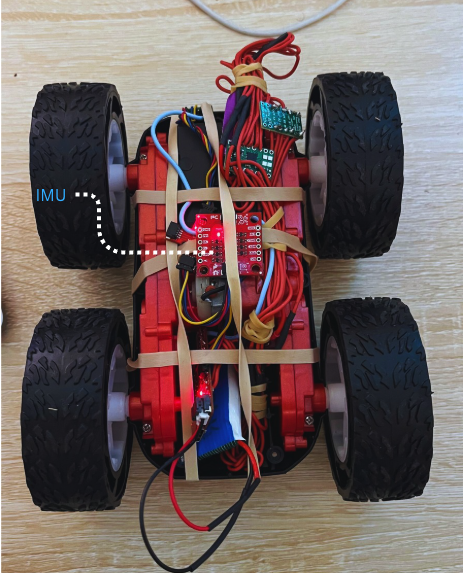
I mounted the IMU securely on my robot chassis, allowing me to experiment with different yaw orientations reliably.
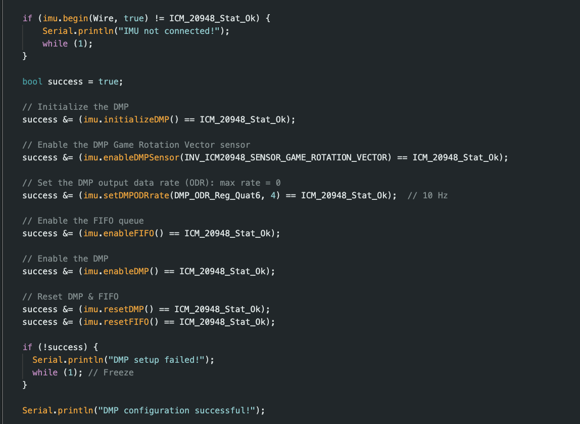
To configure the DMP correctly, I followed the provided DMP tutorial. I uncommented line 29 #define ICM_20948_USE_DMP in the ICM header file and initialized the DMP in my setup().
Then, I enabled the Game Rotation Vector sensor, set the output data rate to the maximum, and enabled both the FIFO and DMP modules. This order of initialization was critical — configuring the DMP before setting up the ICM caused failures during my initial attempts.
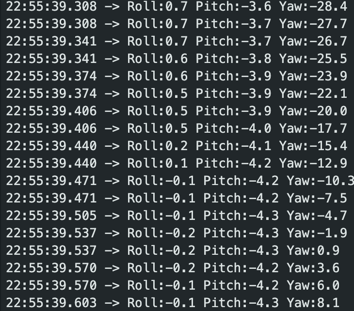
To make sure my DMP was setu correctly and my IMU was correctly responding as expected, I run the example DMP euler file which confirmed yaw values on my serial monitor as I moved my robot clockwise and counter-clockwise.
IMU Integration
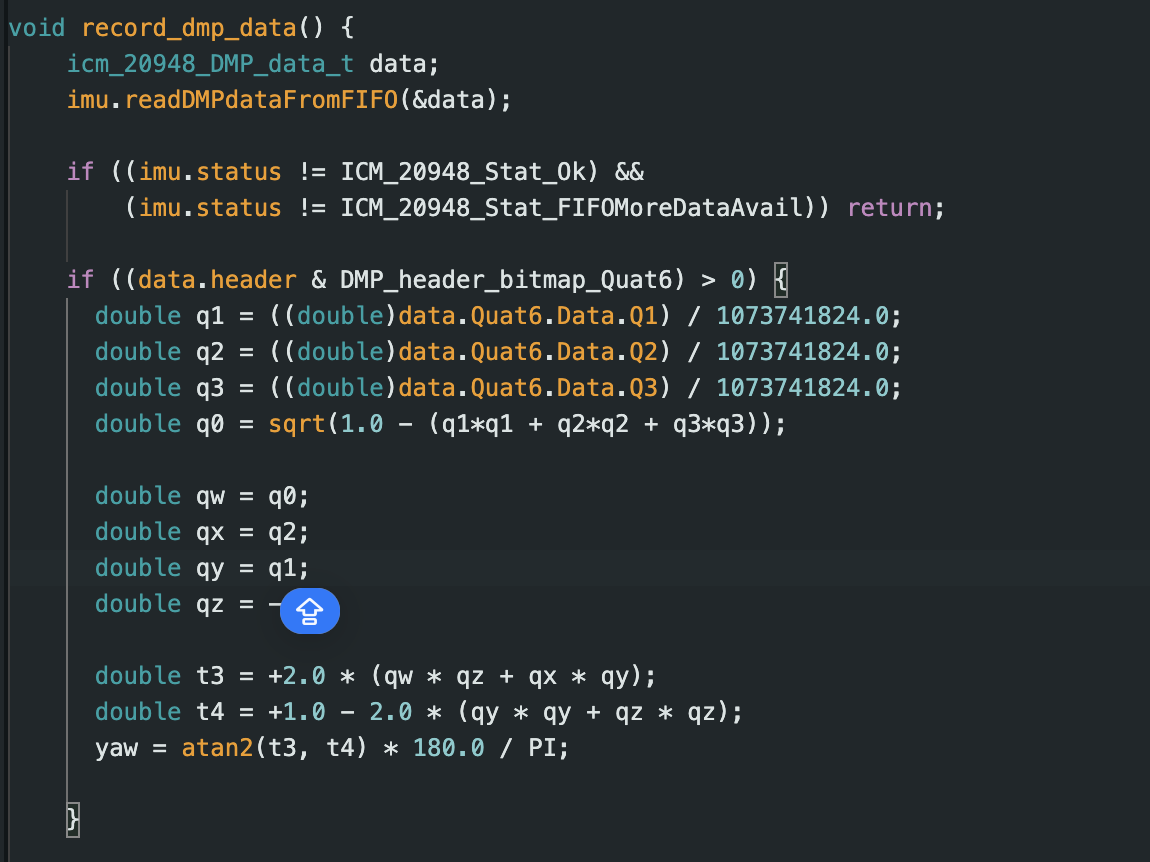
I configured the IMU using the Example7_DMP_Quat6_EulerAngles sketch. The key setup included enabling the GAME_ROTATION_VECTOR sensor, setting the DMP output data rate, and continuously reading the FIFO buffer to prevent overflows. I implemented a record_dmp_data function that extracts yaw from the quaternion data and sends it via BLE for logging.
Bluetooth Commands
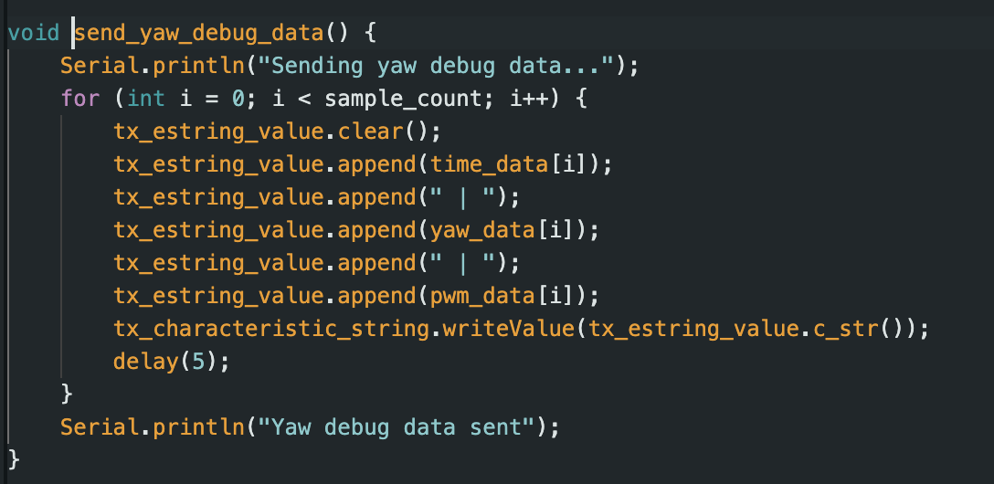
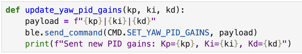
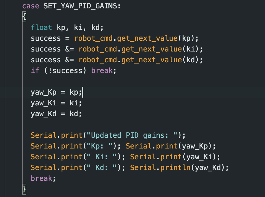
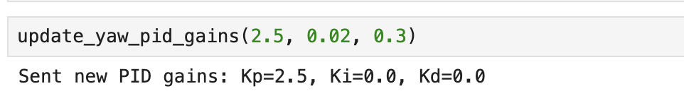
To allow dynamic setpoint adjustment and PID tuning, I created new BLE commands: SET_SETPOINT to update the desired yaw angle and SET_YAW_PID_GAINS for real-time tuning of Kp, Ki, and Kd. A command START_YAW_PID starts the control loop, and SEND_YAW_PID_DATA triggers the Artemis to send yaw, PWM, and timestamped data for plotting.
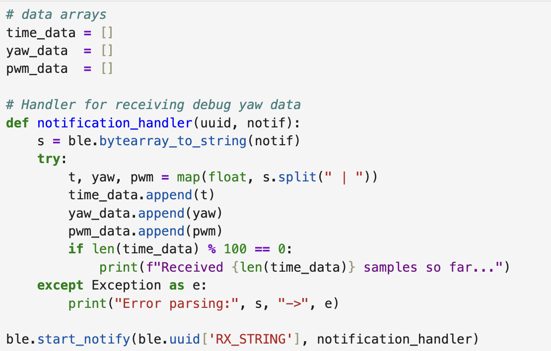
I added a notification handler to receive and handle the incoming yaw, pwm and time data which i would plot for PID analysis.
PID Tuning
I restarted PID tuning with the calibrated motors. I began with proportional-only control using update_yaw_pid_gains() in Python to quickly test values from Kp = 1.0 up to 2.5. At Kp = 1.8, the robot started responding effectively. Beyond that, it overshot and oscillated.
As Kp increased, the robot turned more decisively toward the setpoint but began to overshoot at values more than 1.9. I then added Ki and Kd to reduce steady-state error and dampen oscillations.
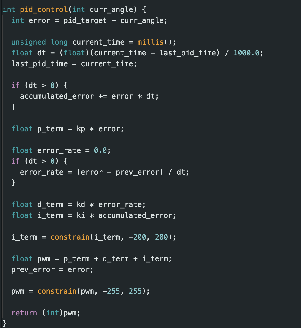
The final values I settled on were: Kp = 1.8, Ki = 0.02, Kd = 0.3. These produced a smooth curve with no sustained oscillation, moderate speed, and quick recovery from disturbances.
As shown in the plot below, the yaw angle initially overshoots due to a large control effort before stabilizing near the target. The PWM signal adjusts dynamically to minimize the yaw error, demonstrating a responsive and functional PID controller.
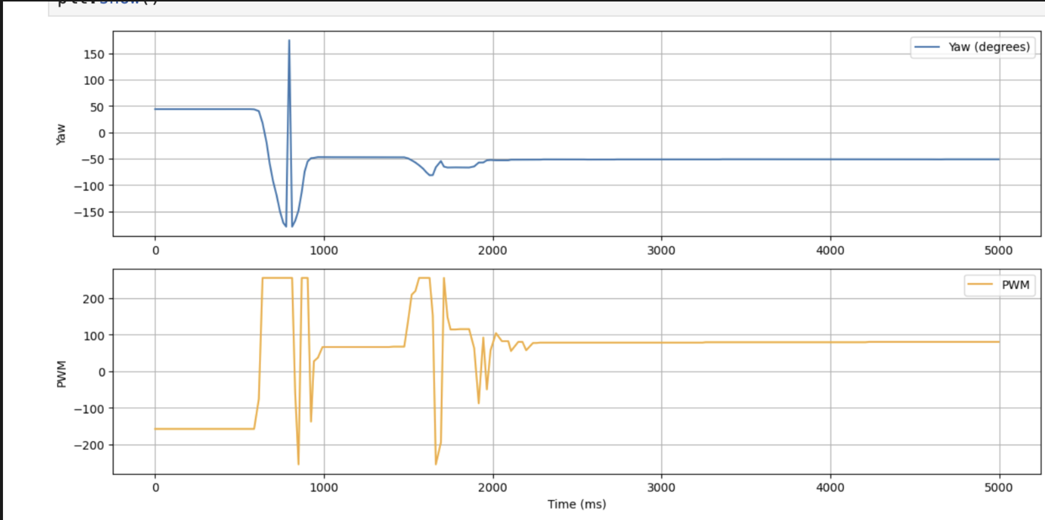
The video below shows the robot executing the yaw PID controller using the final tuned values of Kp = 1.8, Ki = 0.02, and Kd = 0.3. The robot rotates toward the 90° setpoint and settles with minimal overshoot and oscillation.
Conclusion
This lab reinforced my understanding of PID tuning by applying it to angular control. The DMP made a noticeable improvement in yaw stability over using raw gyroscope integration. The ability to update setpoints over BLE allowed for quick iterations, and the final controller was responsive and robust. Minor mechanical adjustments, such as reducing wheel friction, also helped improve the quality of turning.
[1] Huge thanks to Stephan Wagner (2024) for the inspiration and helpful documentation throughout this process.