Lab 5: Linear PID Control

Prelab
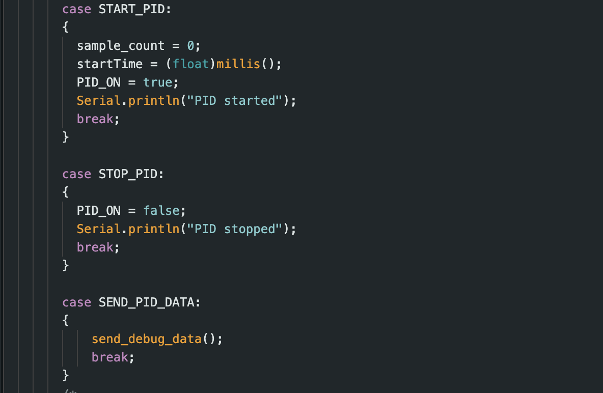
I implemented Bluetooth Low Energy (BLE) communication between the Artemis board and a Python script for wireless command transmission and data reception. This enables real-time debugging and PID parameter tuning without reprogramming, critical for iterative testing. Building on Labs 2 and 3 code, I added PID-specific commands (e.g., starting the PID loop, updating gains) and confirmed the front ToF sensor’s functionality via serial prints.
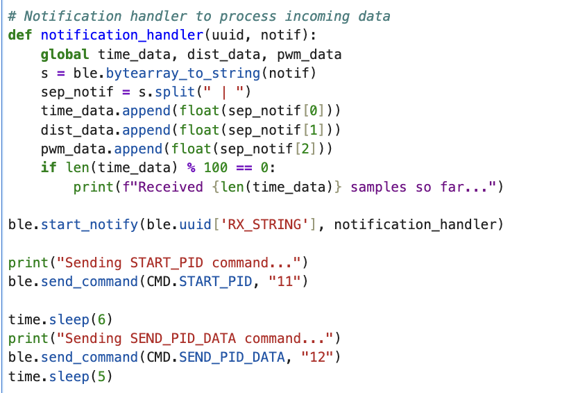
BLE commands facilitated sending instructions and receiving time, distance, PWM, and error data. A Jupyter Notebook notification handler parsed this data into arrays for analysis and graphing, aiding PID tuning.
Lab Tasks
Range and Sampling Time
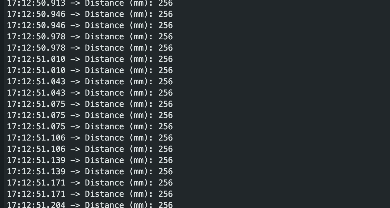
The ToF sensor’s sampling rate, measured via timestamps, is 10 Hz (100 ms interval). Attempts to increase speed using the Pololu library reduced accuracy, so I retained the 100 ms setting for reliability. The PID loop runs at 500 Hz (2 ms interval), meaning it often uses outdated distance data, which may delay responses at higher speeds.
Deadband
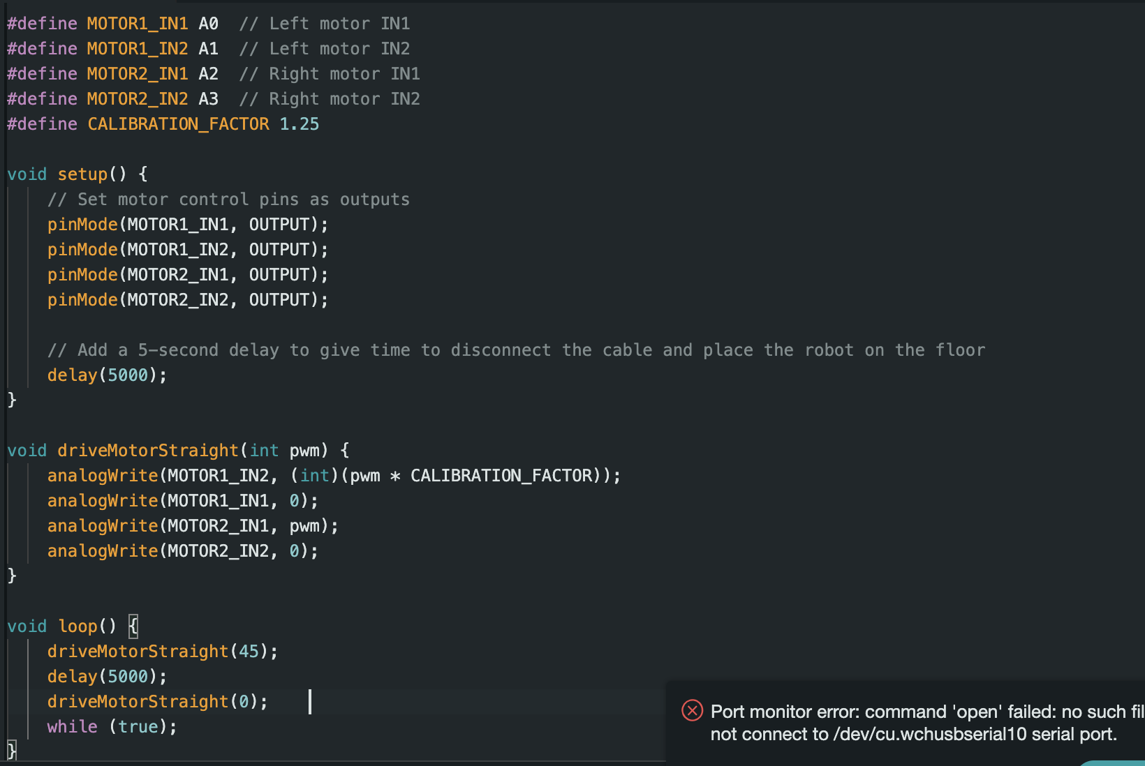
From previous lab, I had set the minimim pwm to 80 but for this lab, with extra experimenting,

Tuning Parameters
To avoid destroying my front mounted tof camera, i begubn the experiment by driving the rc robot into a softer box waller and later moved to a concrete wall when I felt confident on my kp PID value.
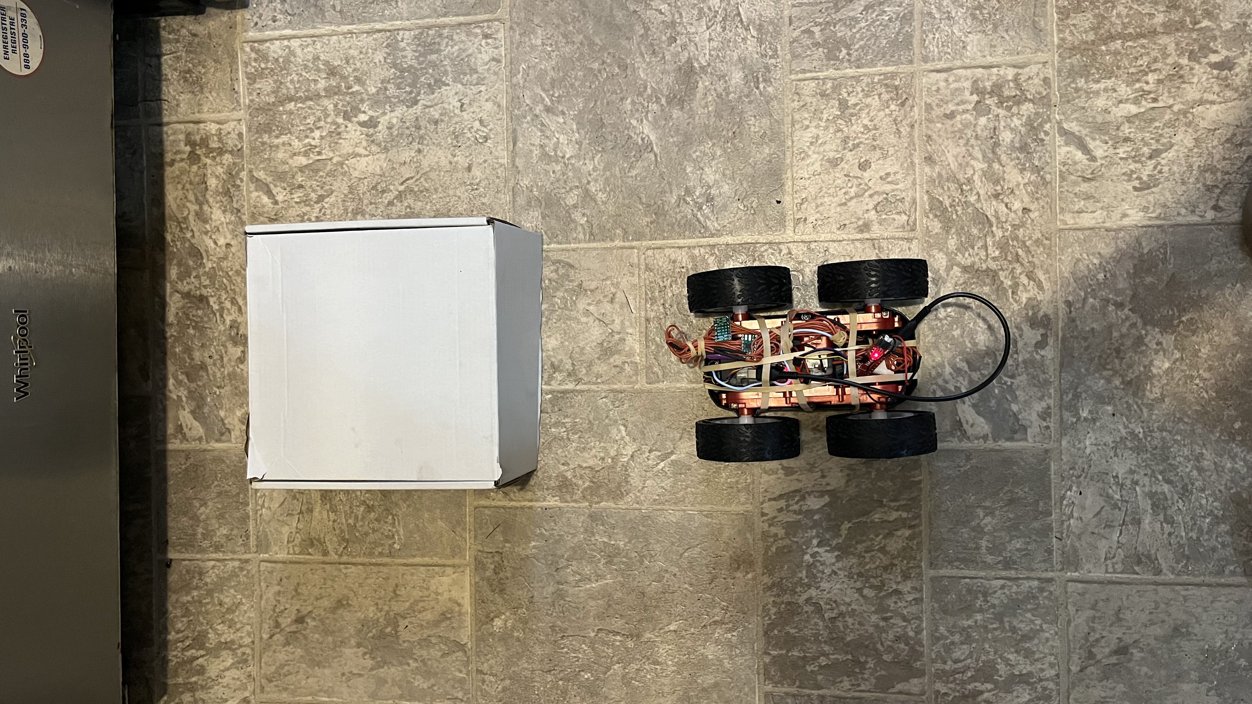
To tune my PID system, I started by setting Kp, Ki, and Kd to zero. I then calculated a theoretical value for Kp and reduced it from this value until the system's oscillations became steady and overshoot was minimized. Next, I increased Ki until the steady-state error (the difference between the target and actual position) was eliminated. Finally, I increased Kd to reduce the amplitude of oscillations.
Starting with a proportional-only controller (Kp = 0.063, Ki = 0.0, Kd = 0.0), the robot approached the wall with a 99 mm overshoot, stopping at 205 mm (tolerance: 20 mm, PWM cap: 150). Adding the derivative term (Kd = 0.1) and adjusting Kp to 0.05 reduced overshoot, while Ki remained 0.0 due to negligible steady-state error. Final values: Kp = 0.05, Kd = 0.1, Ki = 0.0, tolerance = 5 mm.
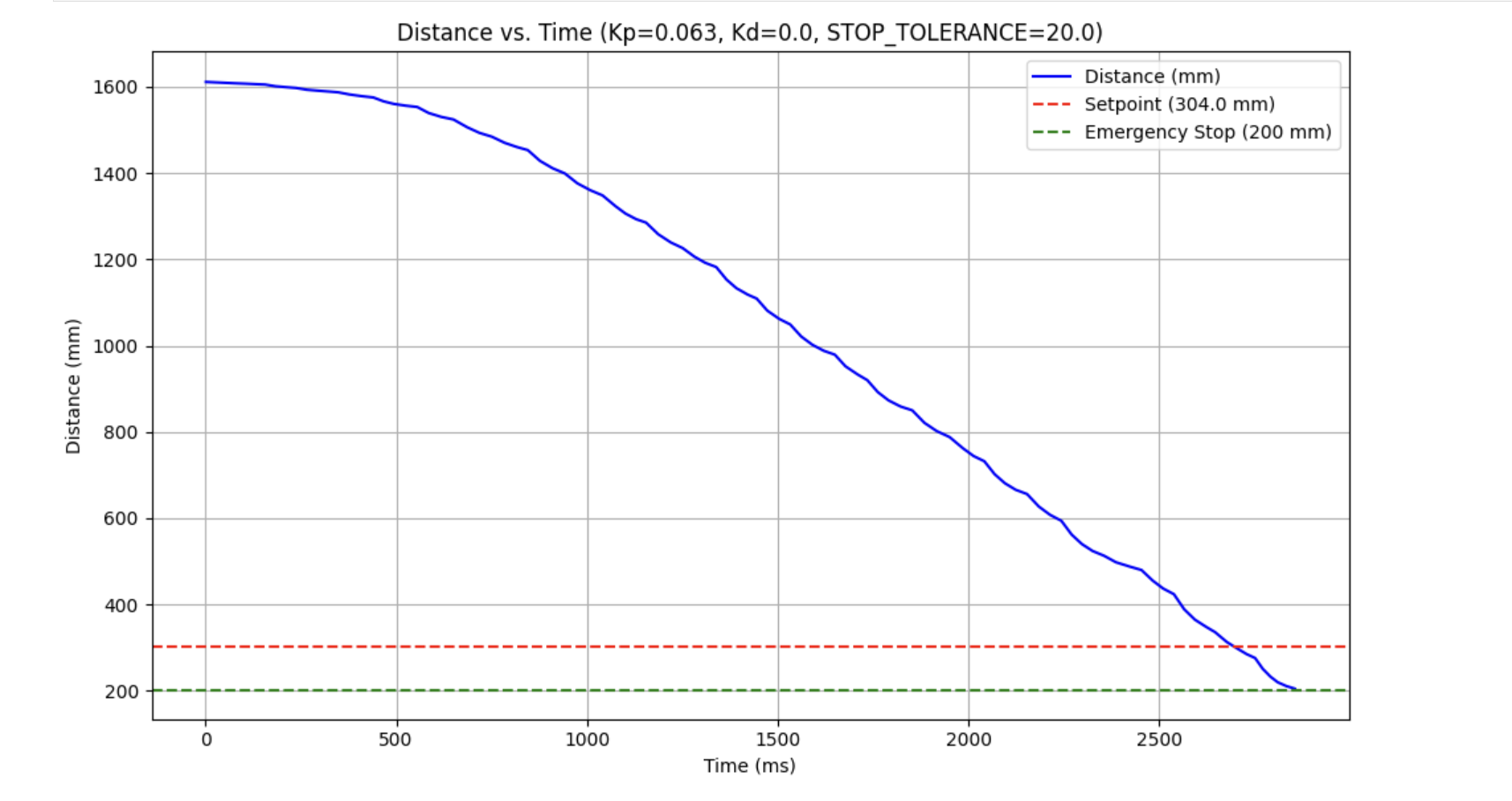
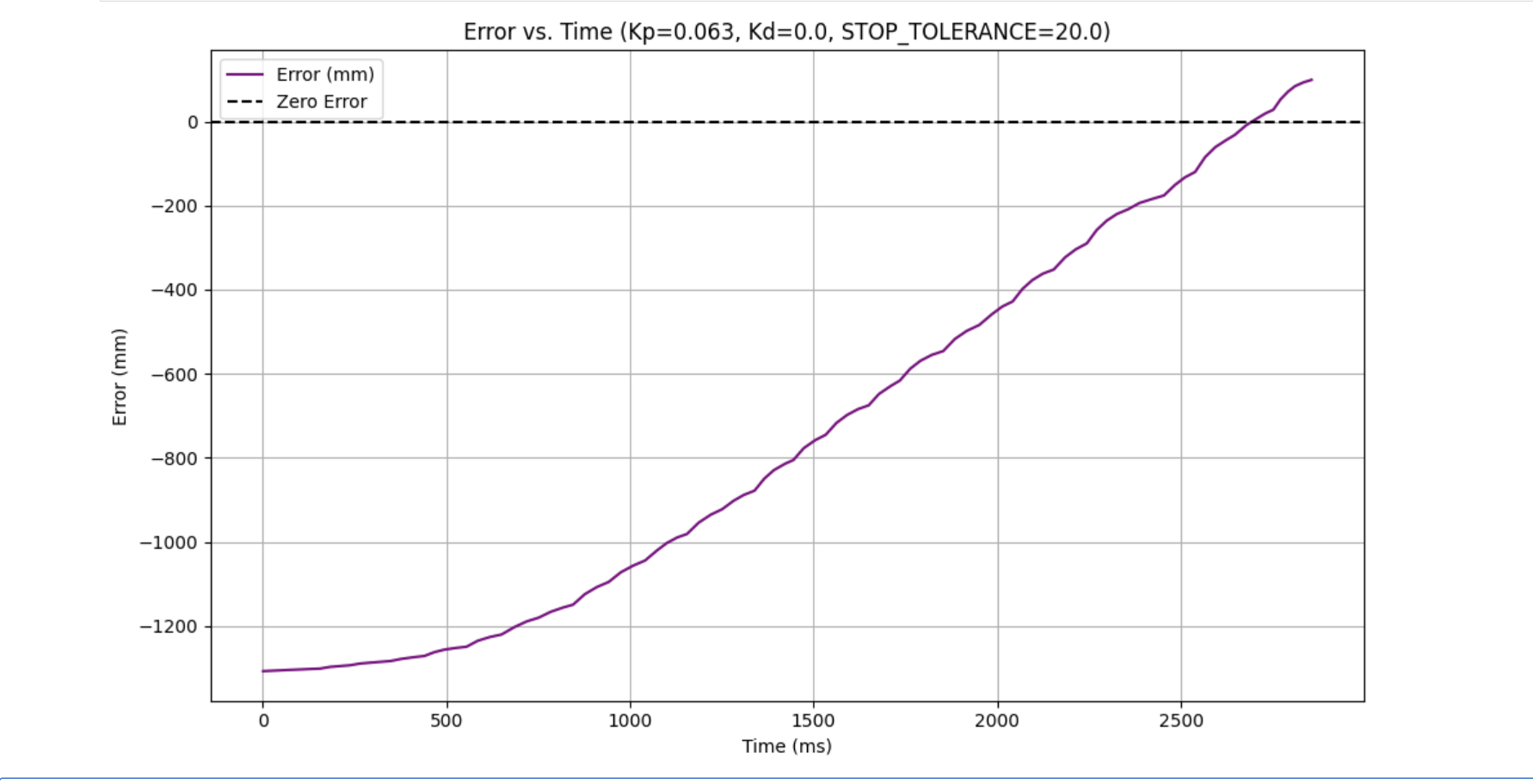
The video shows the robot stopping at 304 mm with minimal overshoot. Three trials confirmed reliability within 5 mm, and the distance vs. time plot indicated a maximum speed of 0.5 m/s.
Extrapolation
To address the ToF’s slow 10 Hz rate, I implemented linear extrapolation for distance estimates between updates.
The PID loop runs at 500 Hz, using new ToF data when available or extrapolating otherwise.
The formula, estimated_distance = last_distance + ((last_distance - previous_distance) / 0.1) * time_since_last,
calculates the current distance using the last two readings and elapsed time.
Note to self and TA: Need to resolder my gnd motor pin, came loose during testing. Video above is just a placeholder