Lab 3: Time of Flight Sensors
Introduction
This lab explored the VL53L1X Time-of-Flight (ToF) sensors on an Artemis Nano, aiming to equip a robot with fast, reliable distance sensing. Tasks included I2C setup, single sensor mode testing, dual sensor operation, and integration with an IMU and Bluetooth.
Prelab
1. Battery Power Preparation
In the future, I hope to connect my Artemis Nano board to an RC car, requiring battery power without a tether to my MacBook. To prepare, I soldered a JST connector to the 750mAh battery from the RC car and used it to power my Artemis. This ensures untethered operation for mobile applications. I cut the battery wires one at a time to avoid shorting, soldered them to the JST jumper (red to positive, black to negative), and insulated with heat shrink. The Artemis powered on successfully via the battery, tested with a simple BLE sketch.

2. Bluetooth Connection Verification
I then leveraged my previous lab’s implementation to send BLE commands to my battery-powered Artemis board, confirming a successful Bluetooth connection. Using a BLE sketch adapted from Lab 1, I powered the Artemis with the soldered JST connector and 650mAh battery, disconnected the USB tether, and send a BLE connection request from my macbook to the battery powered artemis. The video below demonstrates this setup and successful BLE connection.
ToF Connection
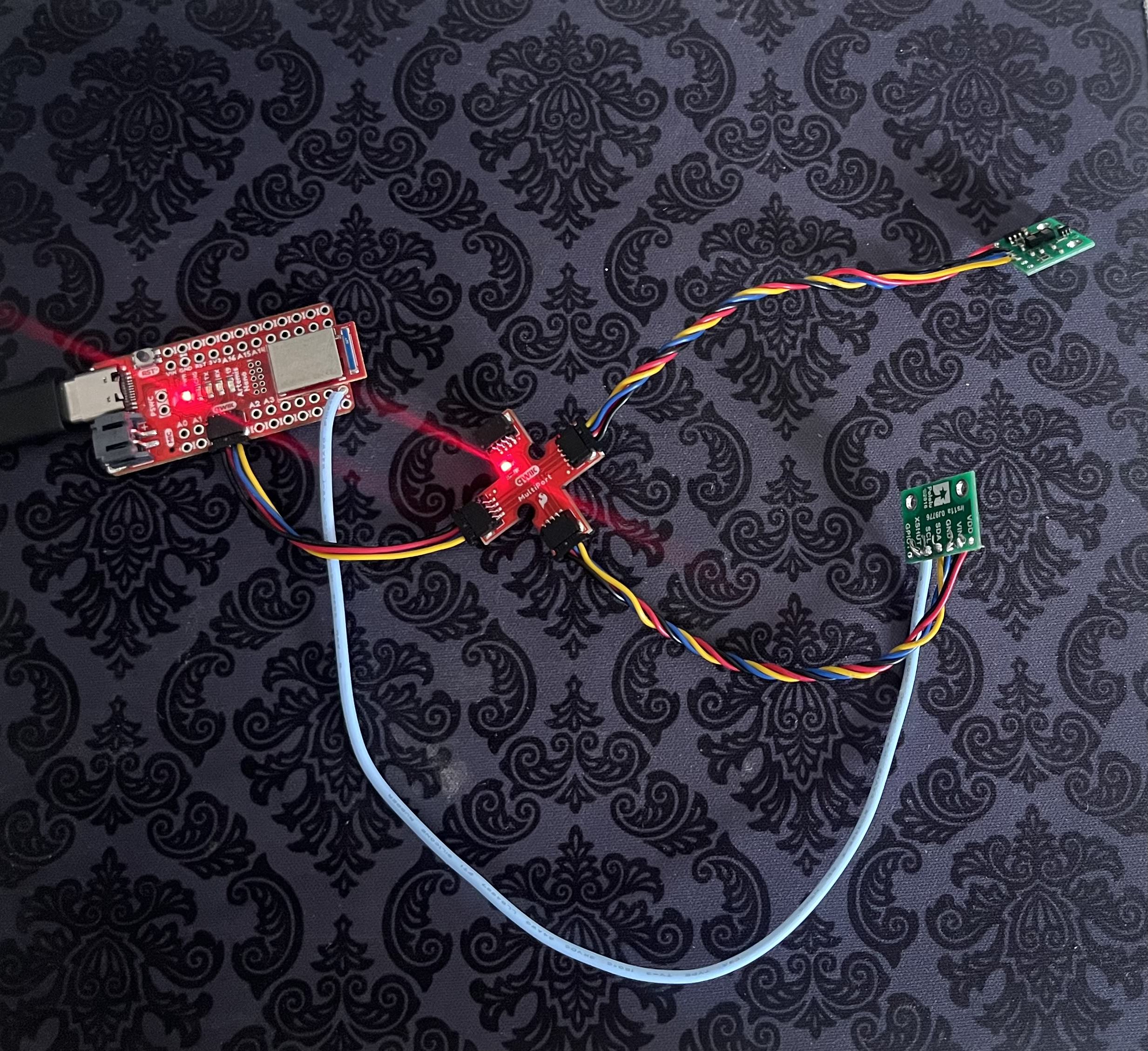
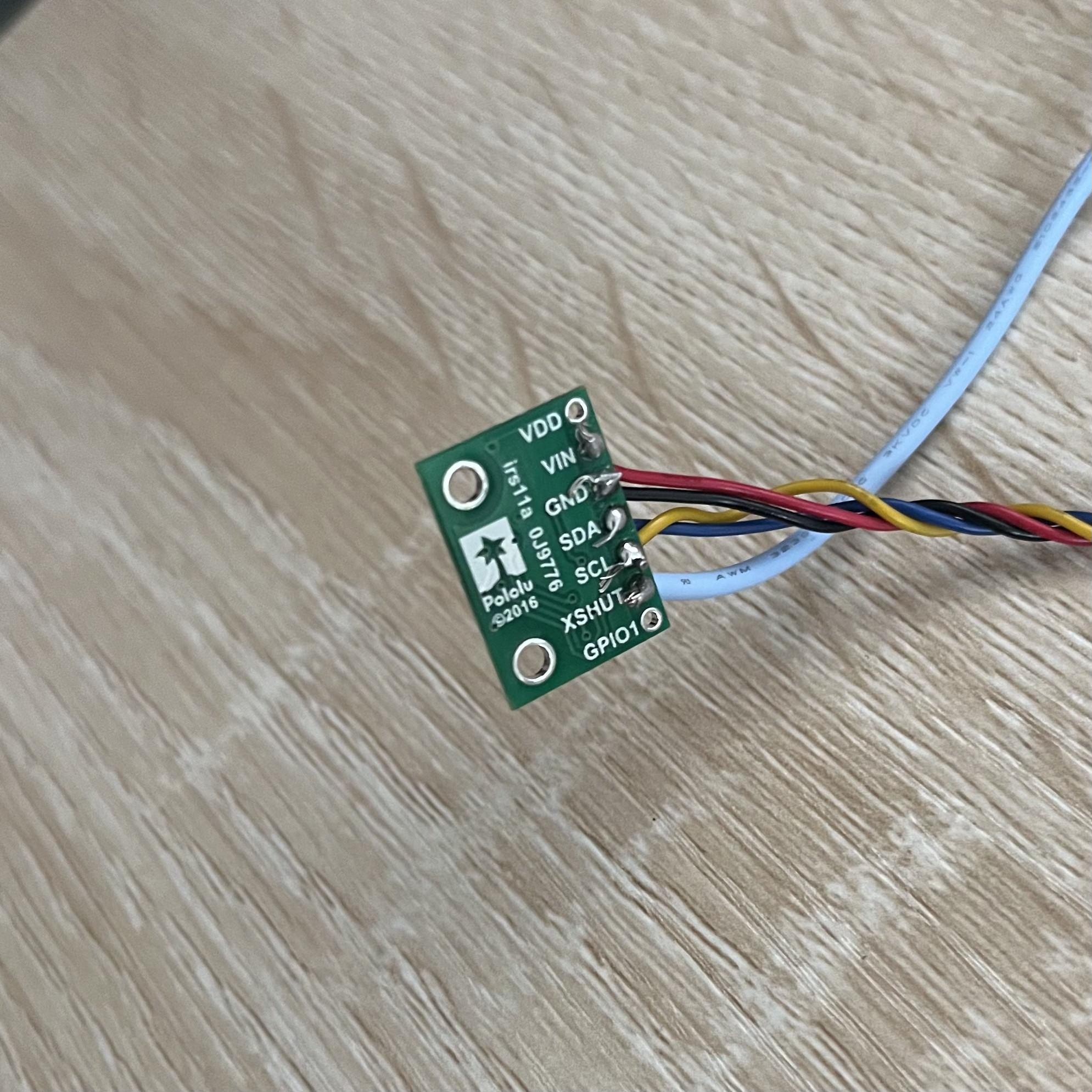
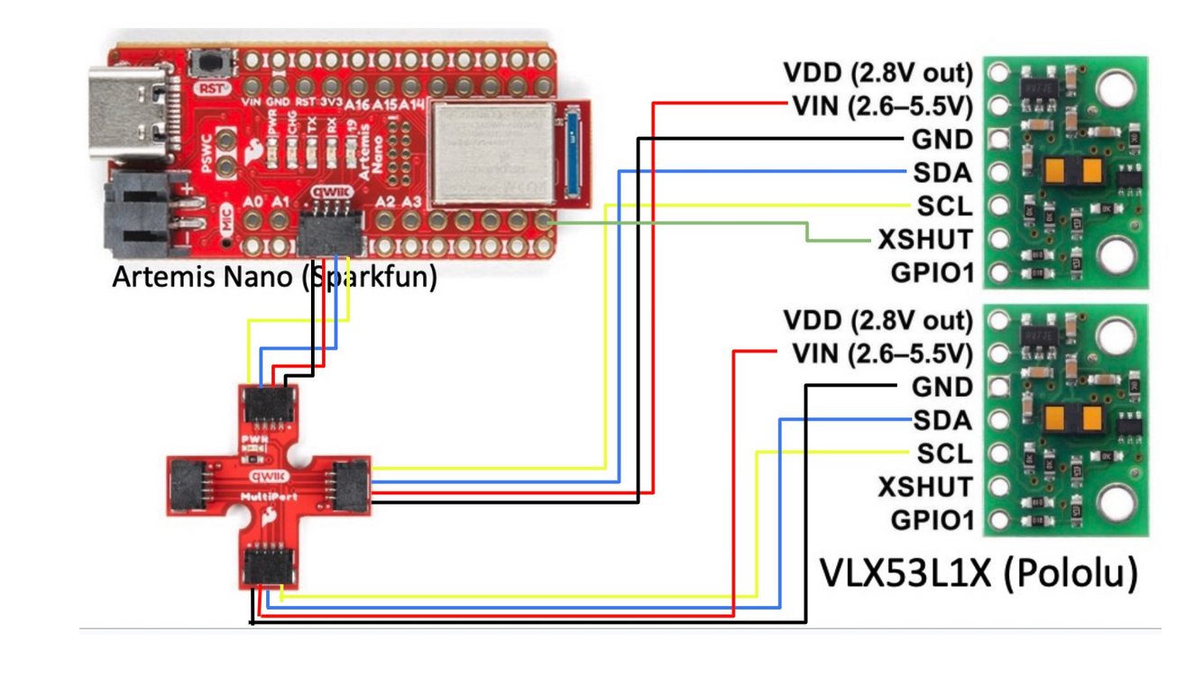
I soldered one of the provided QWIIC cables to the following pins on each VL53L1X ToF board: VIN to the red wire (power), GND to the black wire (ground), SDA for data to the blue wire, and SCL for clock to the yellow wire. This connects both sensors to the Artemis Nano via the QWIIC breakout board, enabling I2C communication.
3. I2C Address
The VL53L1X datasheet specifies a default I2C address of 0x52,however through the Artemis scan, the address was found to be 0x29. This is because the last signifant bit is used for read amd write direction status , therefor the address represented without this bit is shifted to the right 0b1010010 → 0b0101001 (52 -> 29). This operation is equivalent to halving the decimal equivalent.

4. Dual Sensor Approach
To manage two VL53L1X sensors with the same default I2C address (0x29), I used a hybrid method combining hardware and software control.
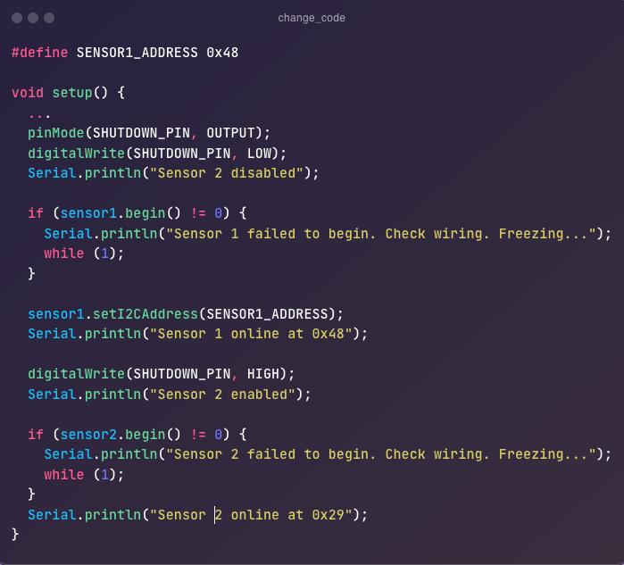
Sensor 2’s XSHUT pin was connected to Artemis pin A8, allowing me to disable it initially by setting A8 LOW.
This isolates Sensor 2, preventing it from responding on the I2C bus.
Meanwhile, Sensor 1, with its XSHUT pin unconnected (always enabled via internal pull-up), initializes first at the default address 0x29.
I then programmatically change Sensor 1’s address to 0x48 using the SparkFun VL53L1X library’s setI2CAddress() function.
After this, I enable Sensor 2 by setting A8 HIGH, allowing it to take the now-vacant 0x29 address.
This approach uses only one GPIO pin (A8) efficiently and ensures both sensors have unique addresses for simultaneous operation.
The decision to use XSHUT with a one-time address change, rather than reprogramming addresses programmatically on every Artemis power-on, was driven by reliability and simplicity. Reprogramming addresses each time requires both sensors to start at 0x29, risking bus conflicts if the sequence fails (e.g., power glitches or code errors). Using XSHUT to disable one sensor during initialization avoids this conflict entirely—only one sensor is active on the bus at a time. Additionally, once Sensor 1’s address is set to 0x48, it persists until power-off, reducing setup complexity on subsequent boots. While changing both addresses programmatically without XSHUT is possible, it demands precise timing and risks failure if the Artemis resets unexpectedly. The hybrid method balances hardware control (XSHUT) with minimal software overhead, making it robust for a battery-powered RC car application.
5. Sensor Placement
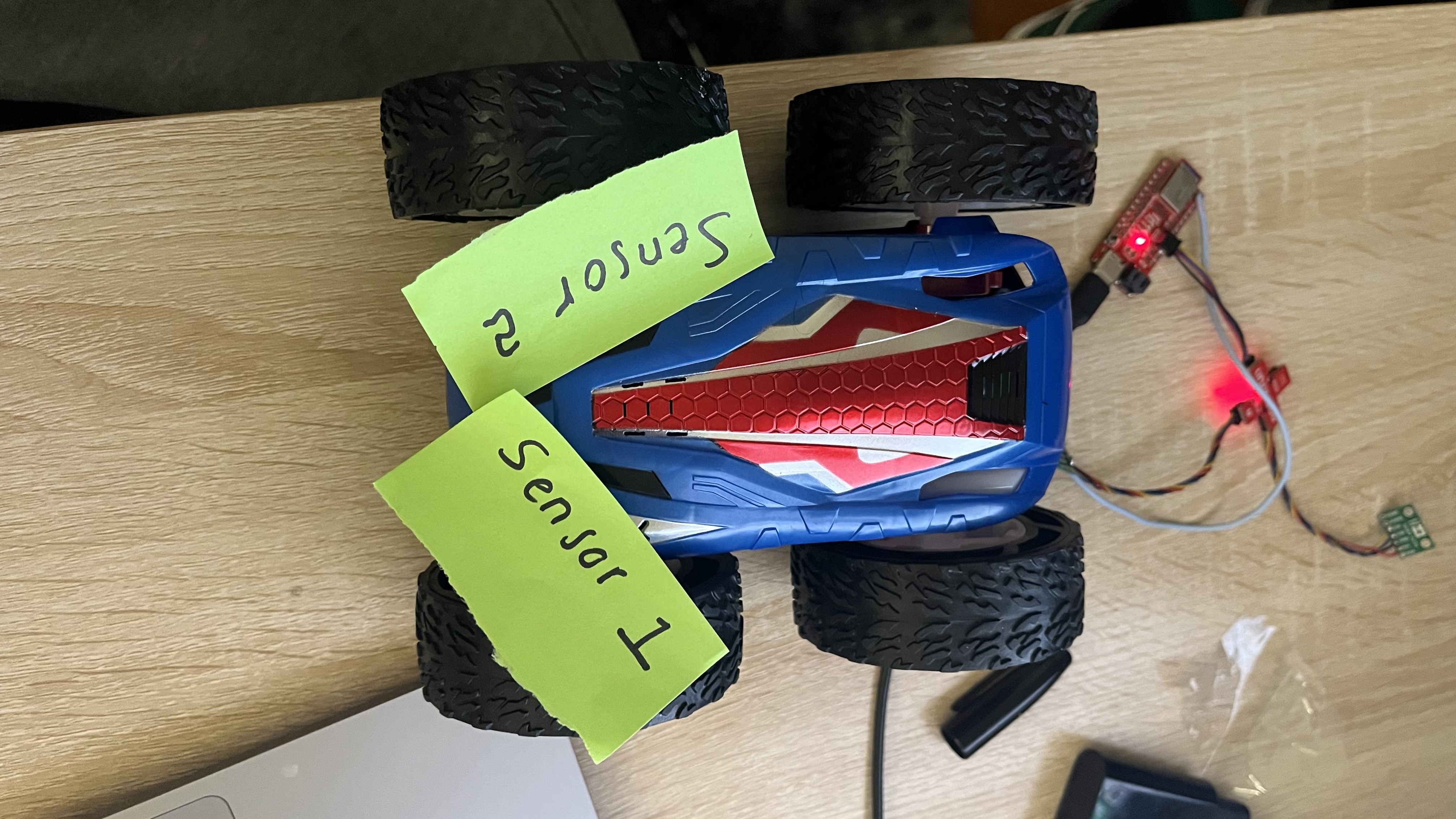
Sensors will be placed front-left and front-right on the robot, angled outward (~15°), to maximize obstacle detection. Blind spots include low objects below sensor height and thin poles between sensors.
6. Wiring Diagram
I wired the VL53L1X sensors using the following sketch, adapted from Wenyi Fu’s design, to reflect my setup. Sketch shows the Artemis Nano connected to the QWIIC breakout board, with Sensor 1 (XSHUT unconnected, always enabled), Sensor 2 (XSHUT connected to Artemis pin A8).
Lab Tasks
1. Single Sensor Mode Data
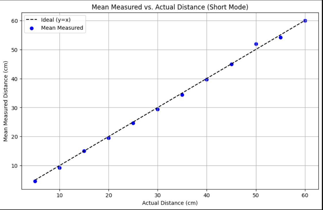
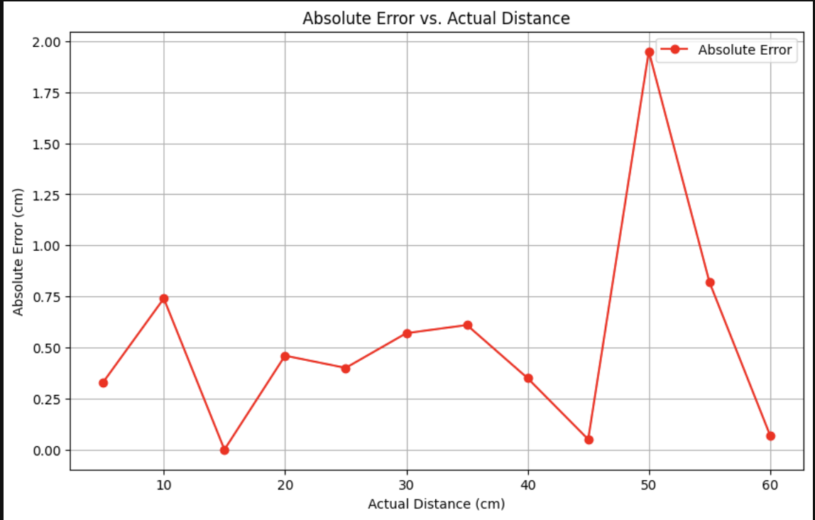
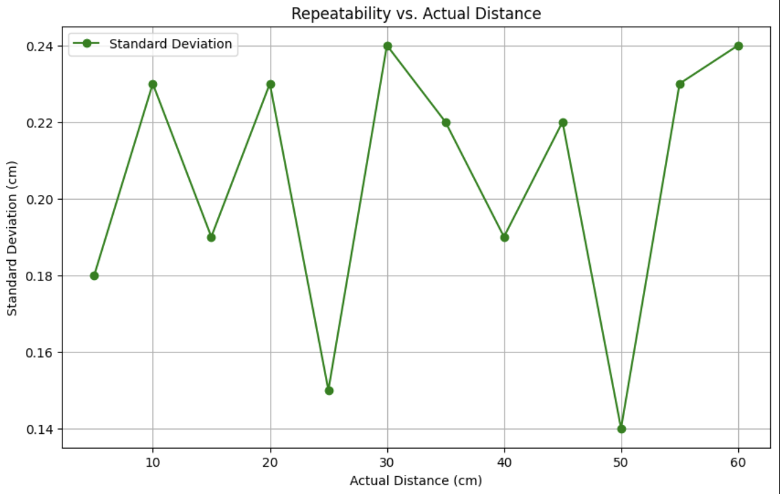
At each distance, I measured 20 data points and calculated the mean and standard deviation to assess the VL53L1X sensor’s performance in Short mode. The mean provided the average measured distance, while the standard deviation informed me about the sensor’s precision (repeatability). I tested distances from 5 cm to 60 cm in 5 cm increments, using a ruler to set actual distances. The table below summarizes the results, and the plots visualize the mean, absolute error, and standard deviation.
2. Dual Sensors
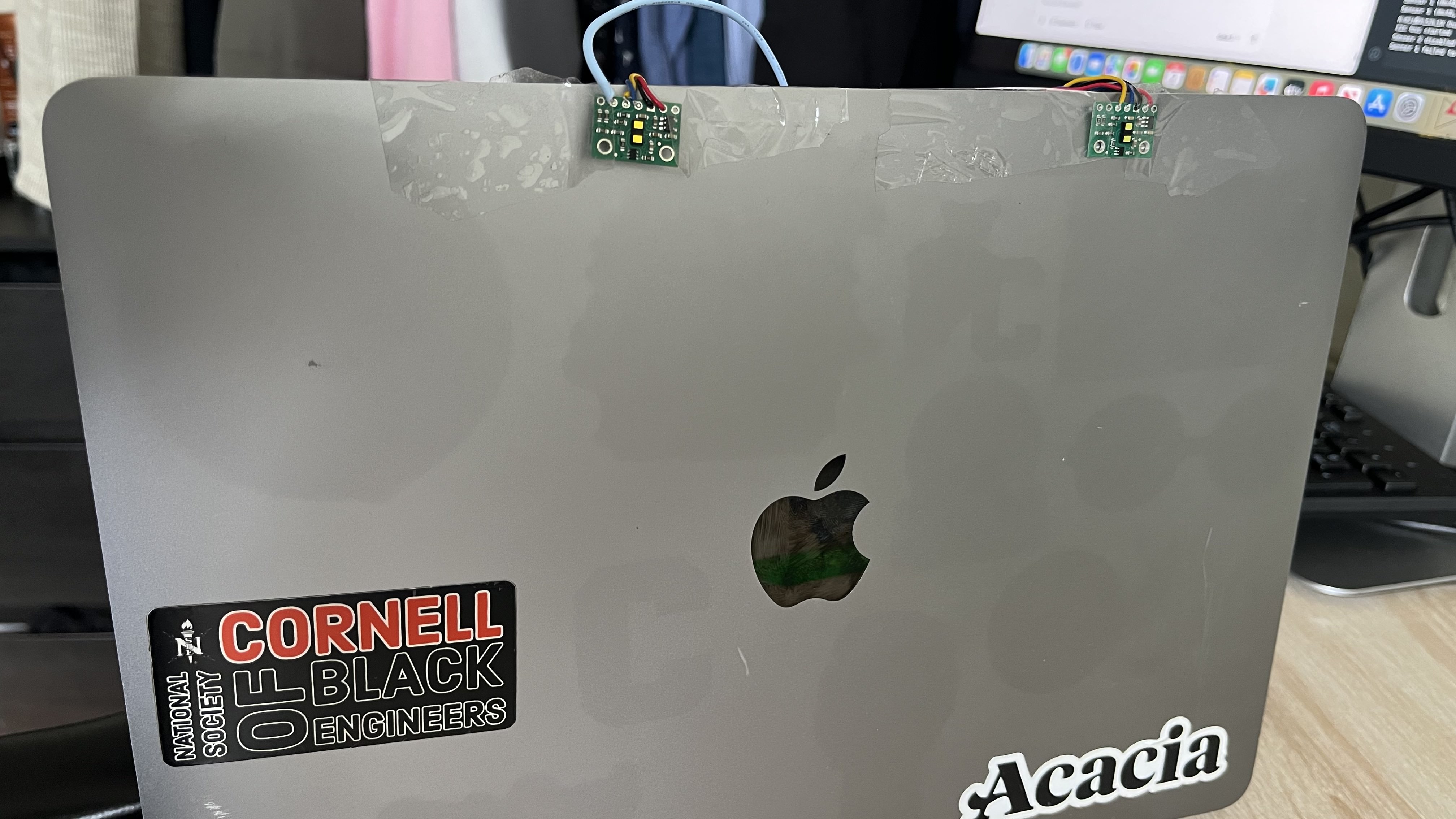
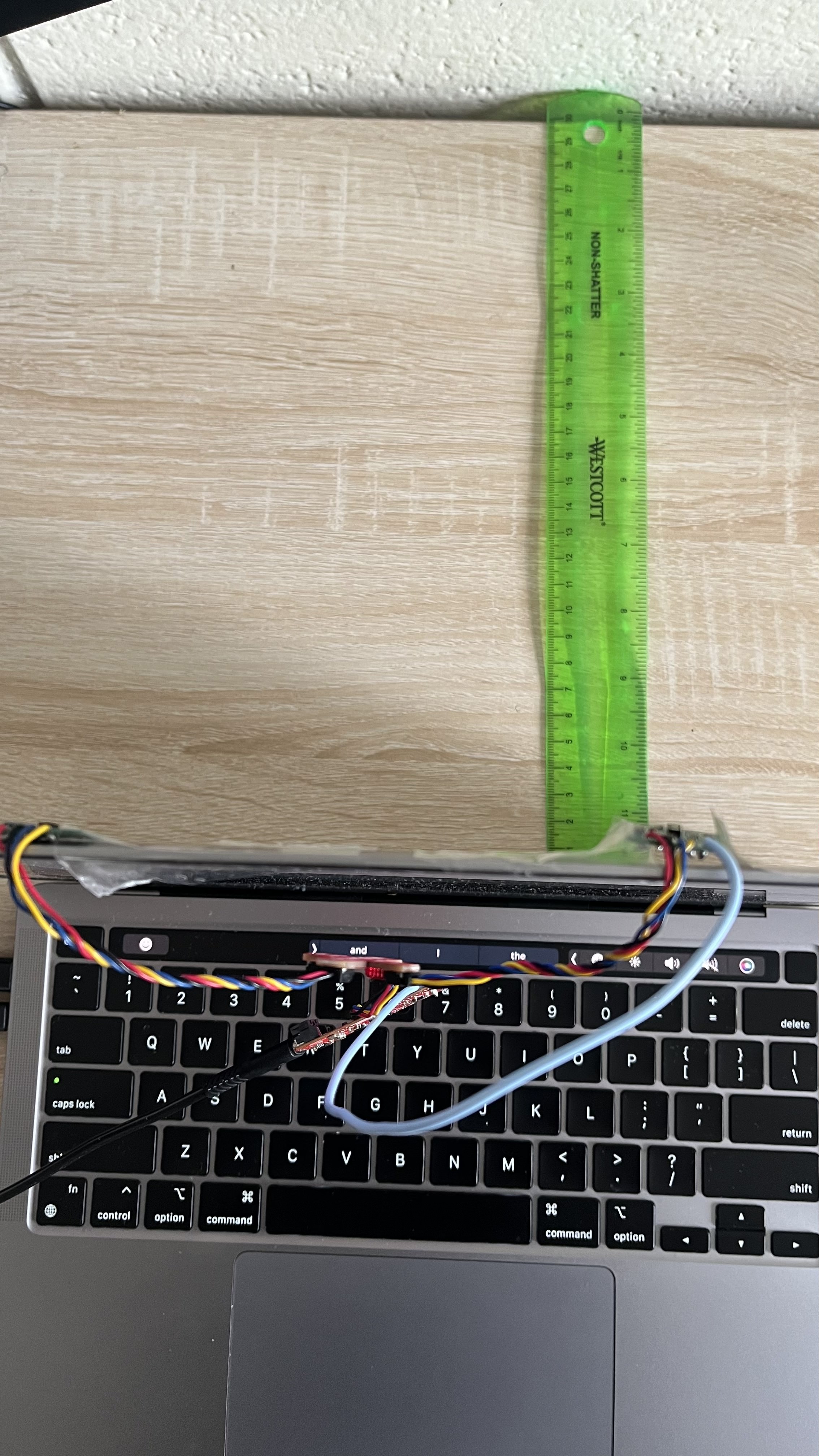
With the sensors wired as described in the ToF Connection section, I set their distance mode to Short and tested them in parallel. I taped the ToF sensors and my laptop in a flat orientation on a table and used a ruler to measure actual distances from my room’s wall. This setup confirmed both sensors operated simultaneously with unique addresses.
3. ToF Sensor Speed
I tested the sensing speed of my dual VL53L1X sensors in Short mode, measuring the loop time to collect and output distances for both sensors.
Using non-blocking reads with checkForDataReady() and millis() timing, I achieved loop times of 4–13 ms, averaging ~10 ms with sensor reads and 4–6 ms without.
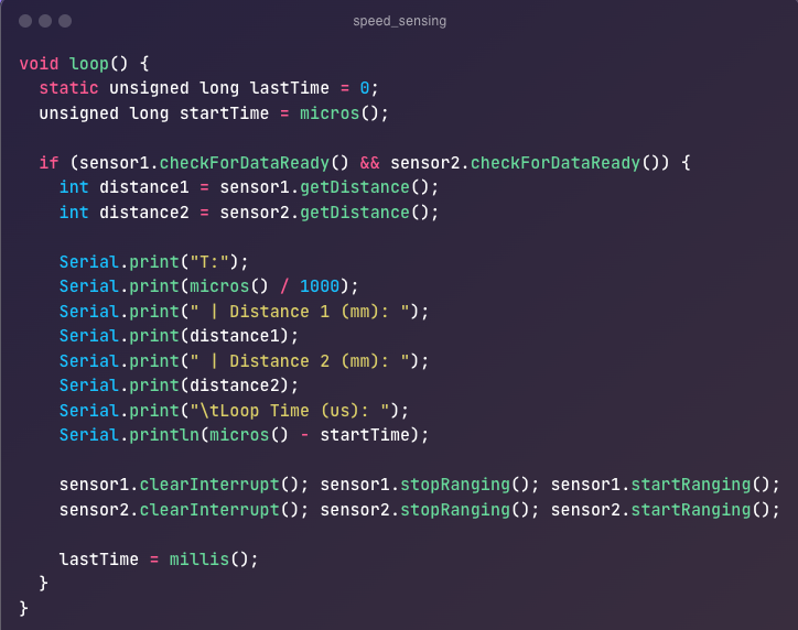
This corresponds to approximately 100 Hz potential, but actual cycles for both sensors take ~100 ms (10 loops), slower than the expected 50 Hz (20 ms per reading) per the datasheet. The primary limiting factor is the sensor ranging time, approximately 50 ms per sensor in Short mode, as specified in the VL53L1X datasheet. Increasing I2C speed to 400 kHz or reducing Serial output could slightly improve speed, but ranging time remains dominant.

4. Time vs. Distance
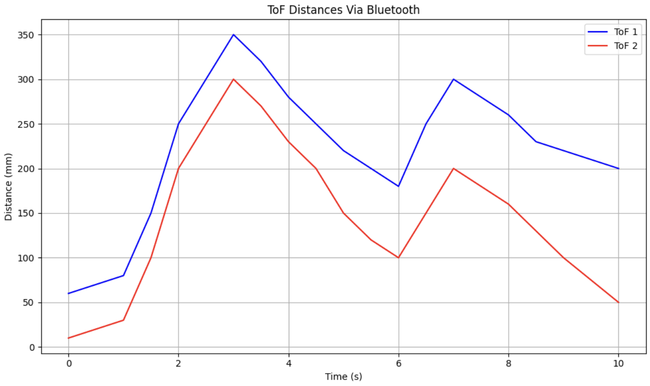
I collected timestamped distance data from both sensors over Bluetooth, and plotted it to analyze performance over time. Both Sensor 1 (ToF 1) and Sensor 2 (ToF 2) operated in Short mode, with distances varying from 60 mm to 350 mm and 10 mm to 300 mm, respectively, reflecting movement or object changes (e.g., objects moving closer then farther over 10 seconds). The plot below shows this data, sent untethered via BLE.
7. Time vs. Angle
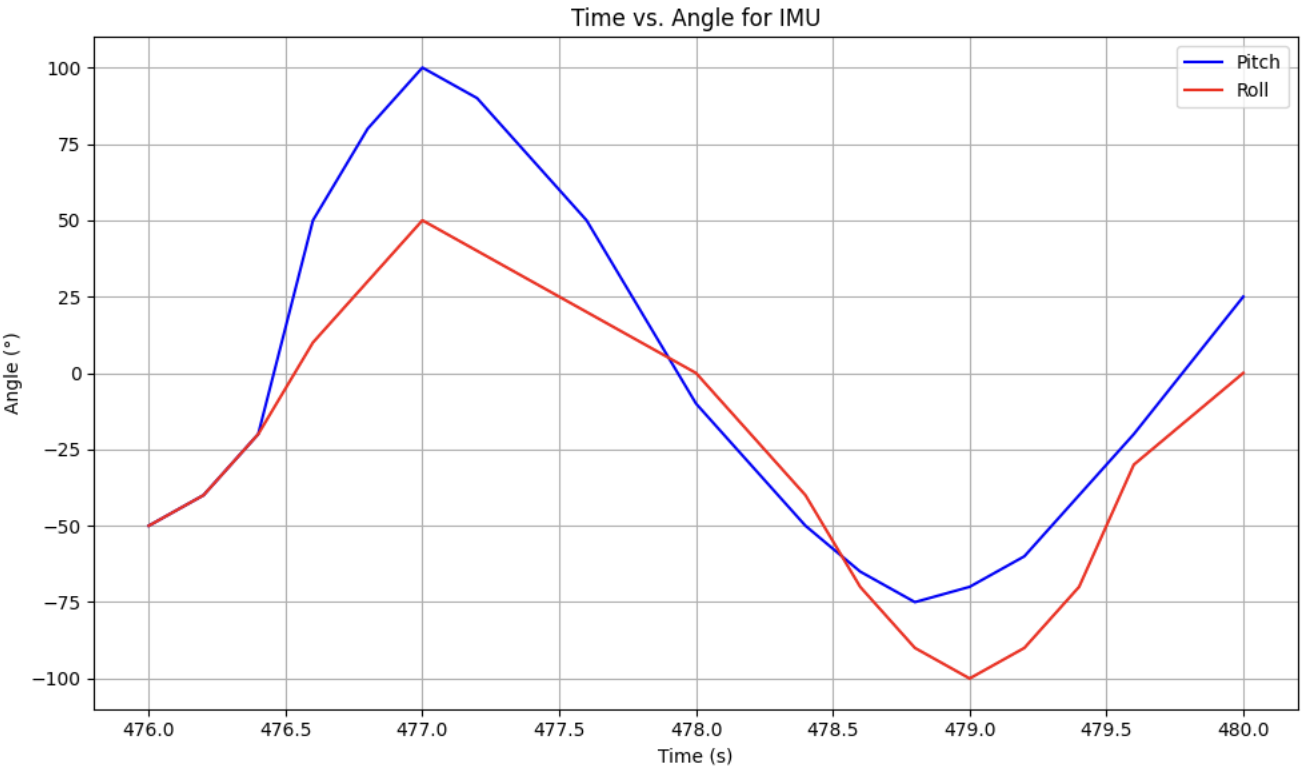
I integrated the IMU, recorded timestamped angle data over Bluetooth, and plotted time vs. angle to analyze the robot’s orientation. The plot below shows this data, sent untethered via BLE.
Conclusion
Overall, this lab was a rewarding experience working with the ToF sensors. I also enjoyed soldering QWIIC cables and the JST connector to the sensors and Artemis board, preparing for the RC untethered operations. This lab demonstrated robust sensor integration and Bluetooth functionality for mobile robotics.