Author: Tony Kariuki
Date: February 10, 2025
This lab focused on setting up and testing the ICM-20948 IMU on the Artemis board.Here i played around and tested the internal workings on the the accelerometer and gyroscope of the IMU.
| SparkFun RedBoard Artemis Nano |
| USB-C cable |
| 9DOF IMU sensor |
| Force1 RC car |
| Li-Ion 3.7V 850mAh battery |
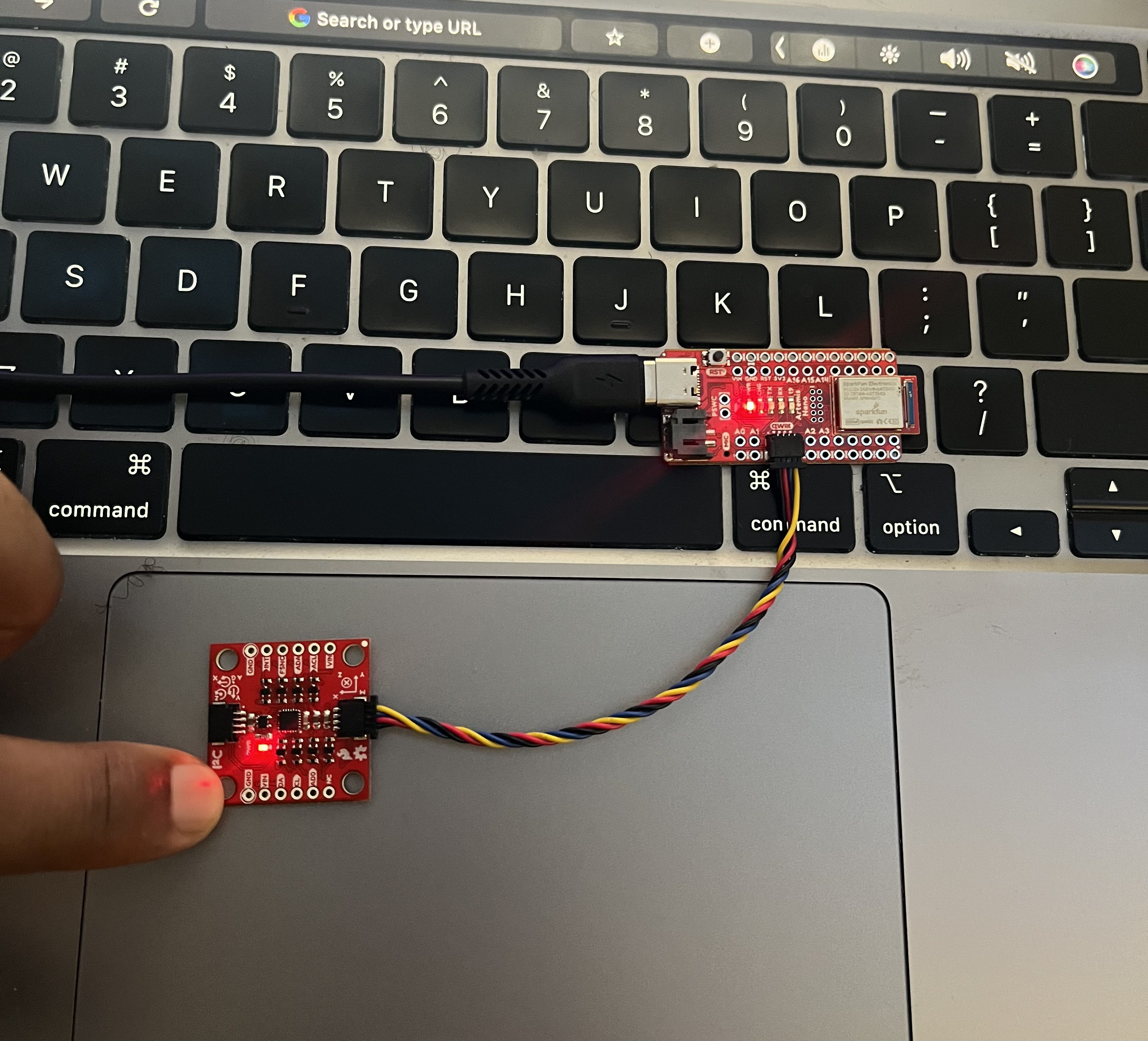
Image: IMU Connections
I tested the IMU by running SparkFun's example sketch
Examples > ICM 20948 > Arduino > Example1_Basics,
which outputs accelerometer, gyroscope, and magnetometer data to the serial monitor.
The AD0_VAL macro, defined at the top of the sketch, sets the last bit of
the IMU's I2C address. I set it to 0 since the ADDR jumper on the Pimoroni board is closed.
The accelerometer measures acceleration relative to gravity, while the gyroscope tracks angular velocity, detecting changes in angle over time from its initial "zero" state at startup. To obtain angular displacement from the gyroscope, its readings must be integrated over time.
To measure the pitch and roll angles using the accelerometer data, I used the following equations form lecture :
        accel_pitch = atan2(myICM.accY(), myICM.accZ()) * 180.0 / M_PI;
        accel_roll  = atan2(myICM.accX(), myICM.accZ()) * 180.0 / M_PI;
To test the IMU calibration , I oriented the IMU at various angles to induce angles of -90, 0 and 90 degress to measure pitch and roll at this angles. The accelemoter pitch and data values received were off by a couple of degrees hence a need for a two point calibration.
To calibrate the accelerometer data, I measured the output of the accelemoter at both -90, 0 and 90 and found the offset of this data to match the desired output.
 pitch_values = incoming_pitch_data
pitch_offset = -np.mean(pitch_values) float pitch_offset = 0.9476842105263155;
float roll_offset = 0.16389473684210526;
void calculatePitchRoll(float ax, float ay, float az)
pitch = atan2(ay, az) * 180.0 / M_PI + pitch_offset;
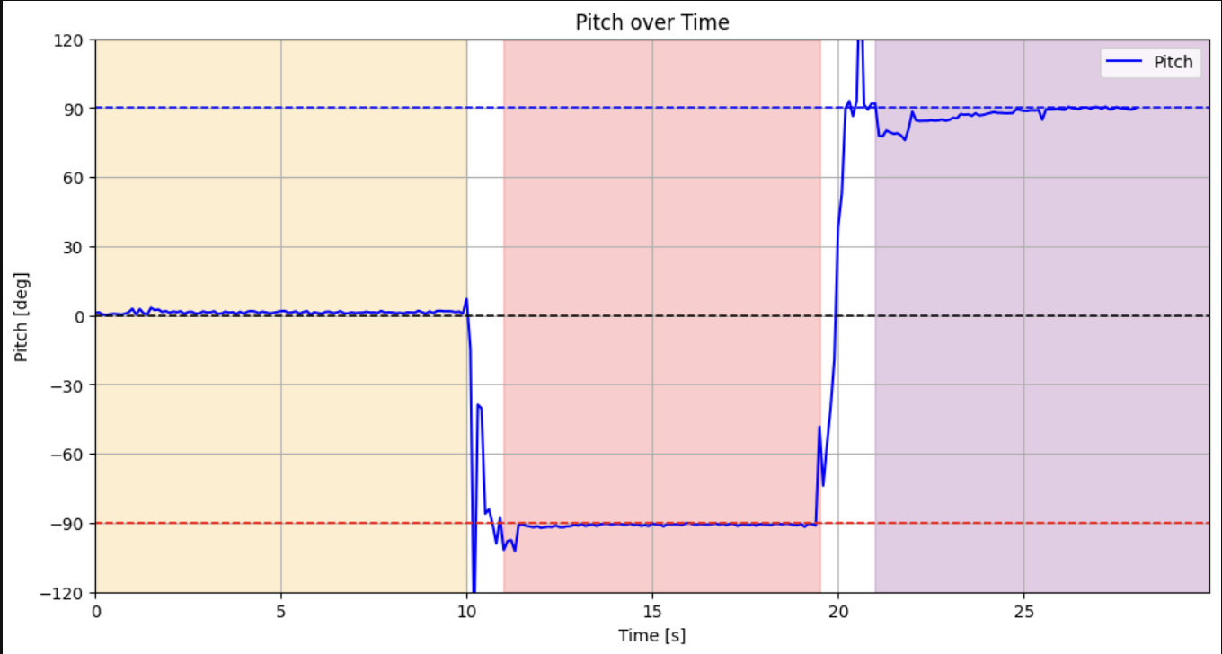
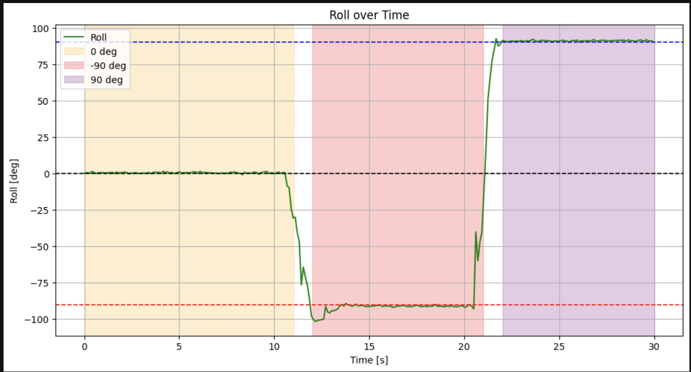
roll = atan2(ax, az) * 180.0 / M_PI + roll_offset; Shown below are the plots of pitch and roll at these various angles after the two point calibration. The highlighted regions indicate times when the IMU was pressed flush on 0 and (-90 , 90) degrees on my desk. The noise seen here is me changing the IMU orientation from angle to angle.
accel_pitch = atan2(myICM.accY(), myICM.accZ()) * 180.0 / M_PI;
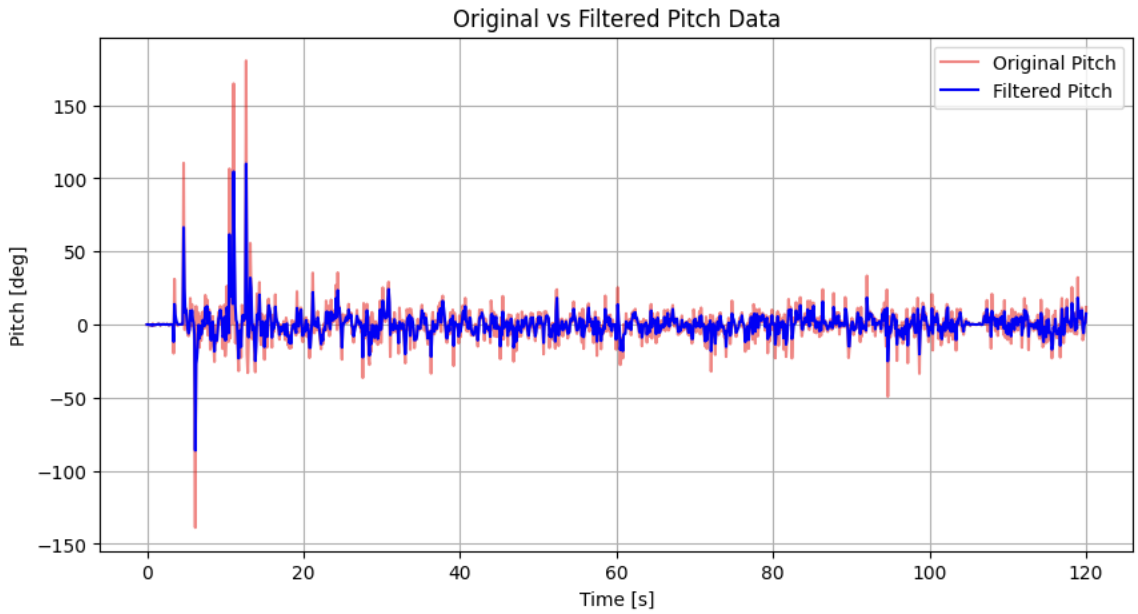
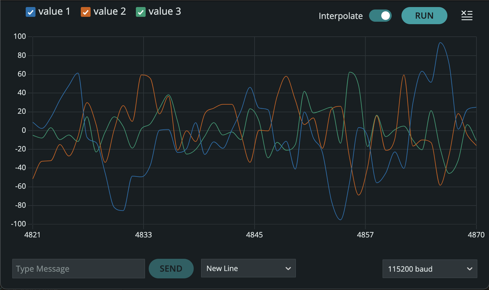
accel_roll = atan2(myICM.accX(), myICM.accZ()) * 180.0 / M_PI; To mitigate noise in the accelerometer data, i recorded periodic imu tilts, transmitted the data via bluetooth, and applied fourier spectrum analysis using scipy's fft() to detect periodic components in the signal. Given my sampling period of 0.1064 sec, i determined a safe low-pass filter cutoff at 1.5 hz based on the frequency spectrum.
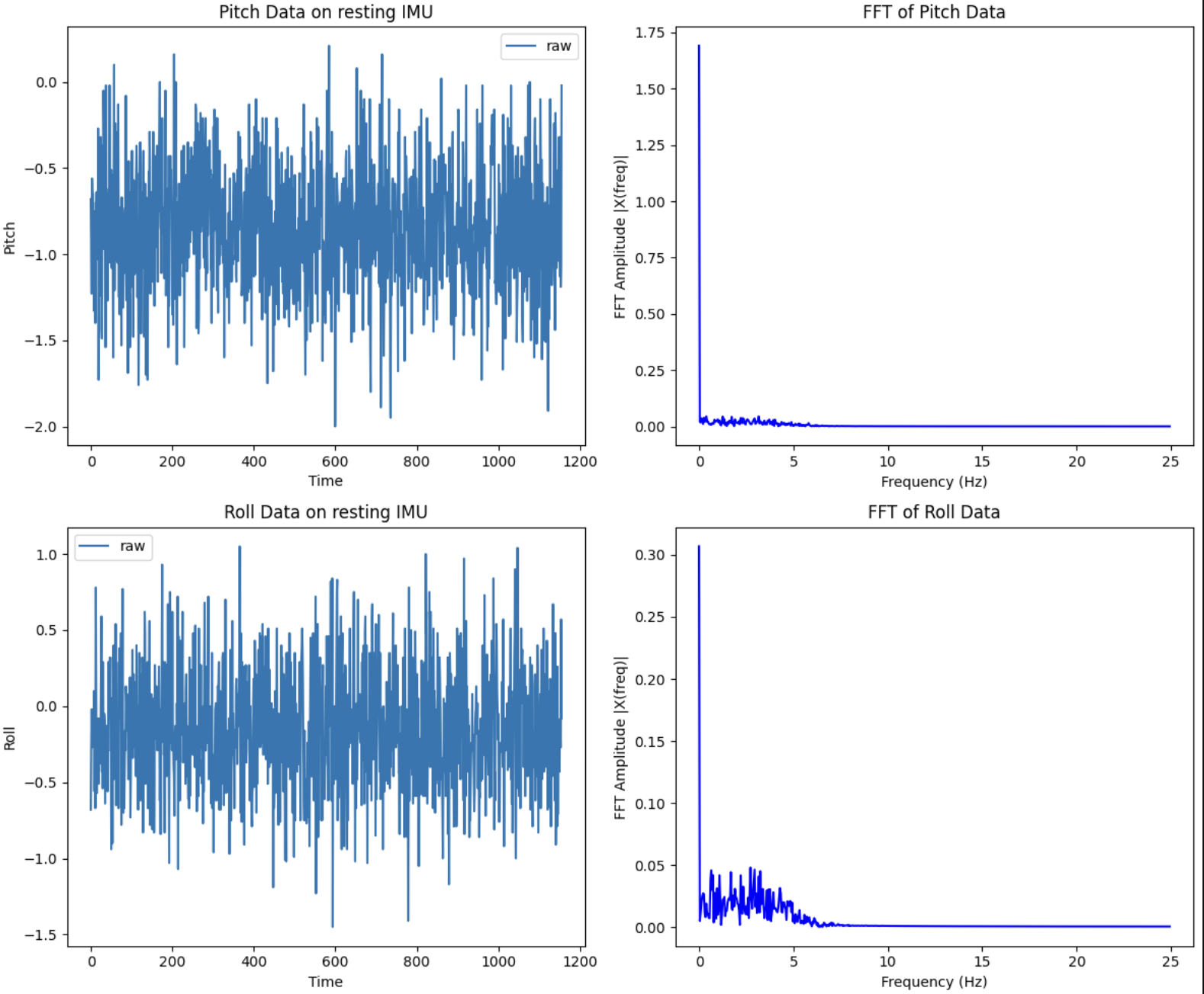
Using my sample period of 0.1064 s and a chosen cut-off frequency of 1.5Hz, I calculated my \(\alpha\) to be roughly 0.60.
I implemented a low pass filter using the equation provided in class.
The low pass filter cuts down on the high frequency noise in the acclerometer data.
For pitch, roll and taw from the gyroscope, I used and implemented the equations from class to measure the gyroscope data over time
float dt = (millis() - lastT) / 1000.;
lastT = millis();
gyro_pitch_raw[i] += myICM.gyrY() * dt;
gyro_roll_raw[i] += myICM.gyrX() * dt;
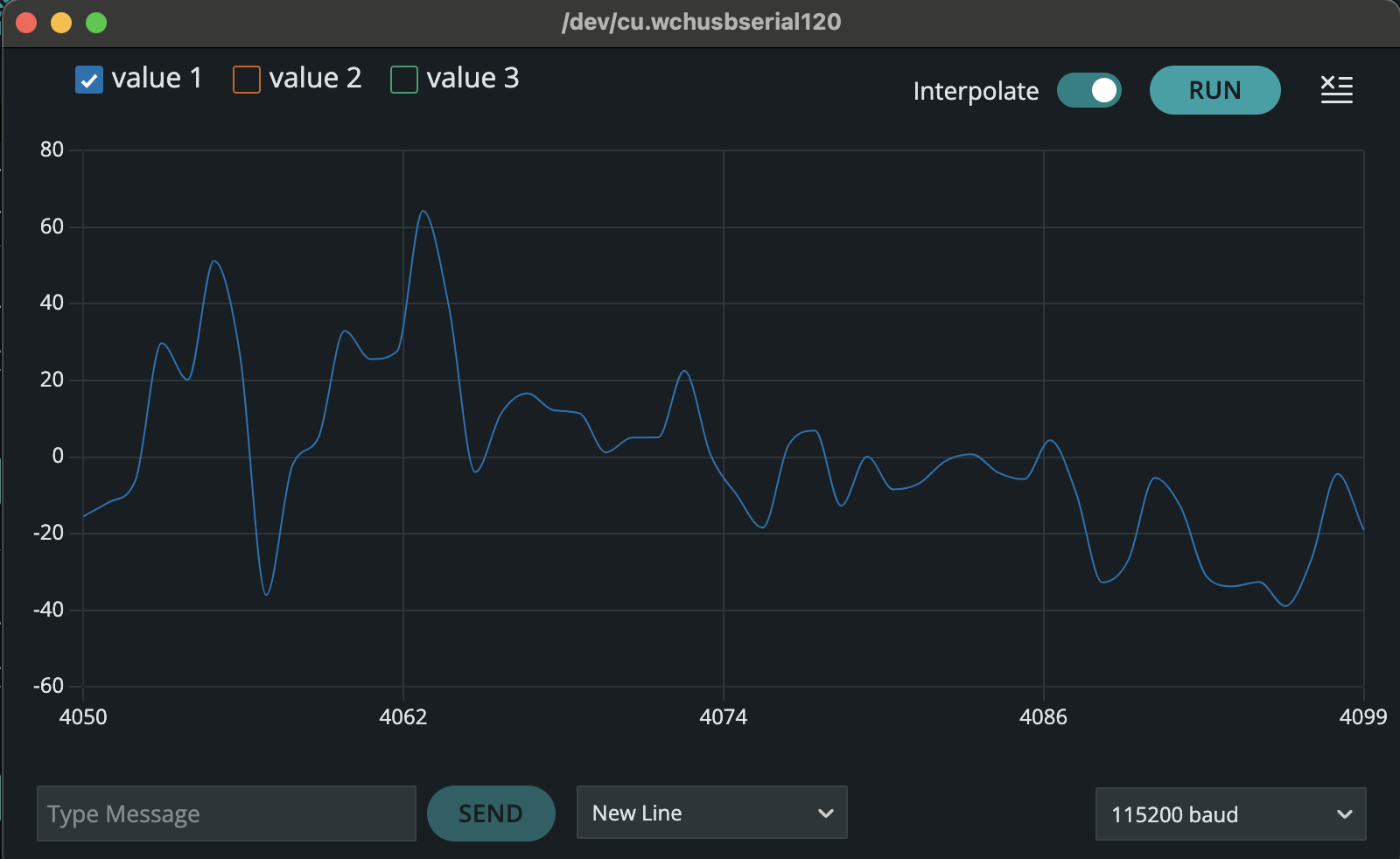
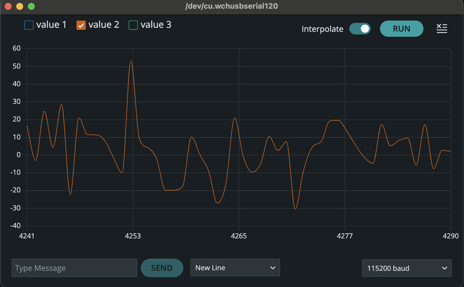
gyro_yaw_raw[i] += myICM.gyrZ() * dt;Just as I did with the acclerometer, i measured the groscope data across the three degrees to induce pitch and roll. The measured was very noisy and as seen from the collected data, the gyroscope drifts over time.
When measuring gyroscope data, I observed noticeable drift over extended data collection periods. While it was less noisy than the accelerometer, it was also less accurate over time. To compensate, I implemented a complementary filter that combines both sensor readings. Based on my FFT analysis, I applied a low-pass filter to the accelerometer data with a 5 Hz cutoff frequency and weighted the gyroscope data more heavily in the fusion process.
    // Accelerometer-based pitch & roll
    accel_pitch = atan2(myICM.accY(), myICM.accZ()) * 180.0 / M_PI;
    accel_roll  = atan2(myICM.accX(), myICM.accZ()) * 180.0 / M_PI;

    // integrate gyro data
    gyro_pitch += myICM.gyrY() * dt;
    gyro_roll  += myICM.gyrX() * dt;

    // complementary filter
    comp_pitch = alpha * (comp_pitch + myICM.gyrY() * dt) + (1 - alpha) * accel_pitch;
    comp_roll  = alpha * (comp_roll + myICM.gyrX() * dt) + (1 - alpha) * accel_roll;
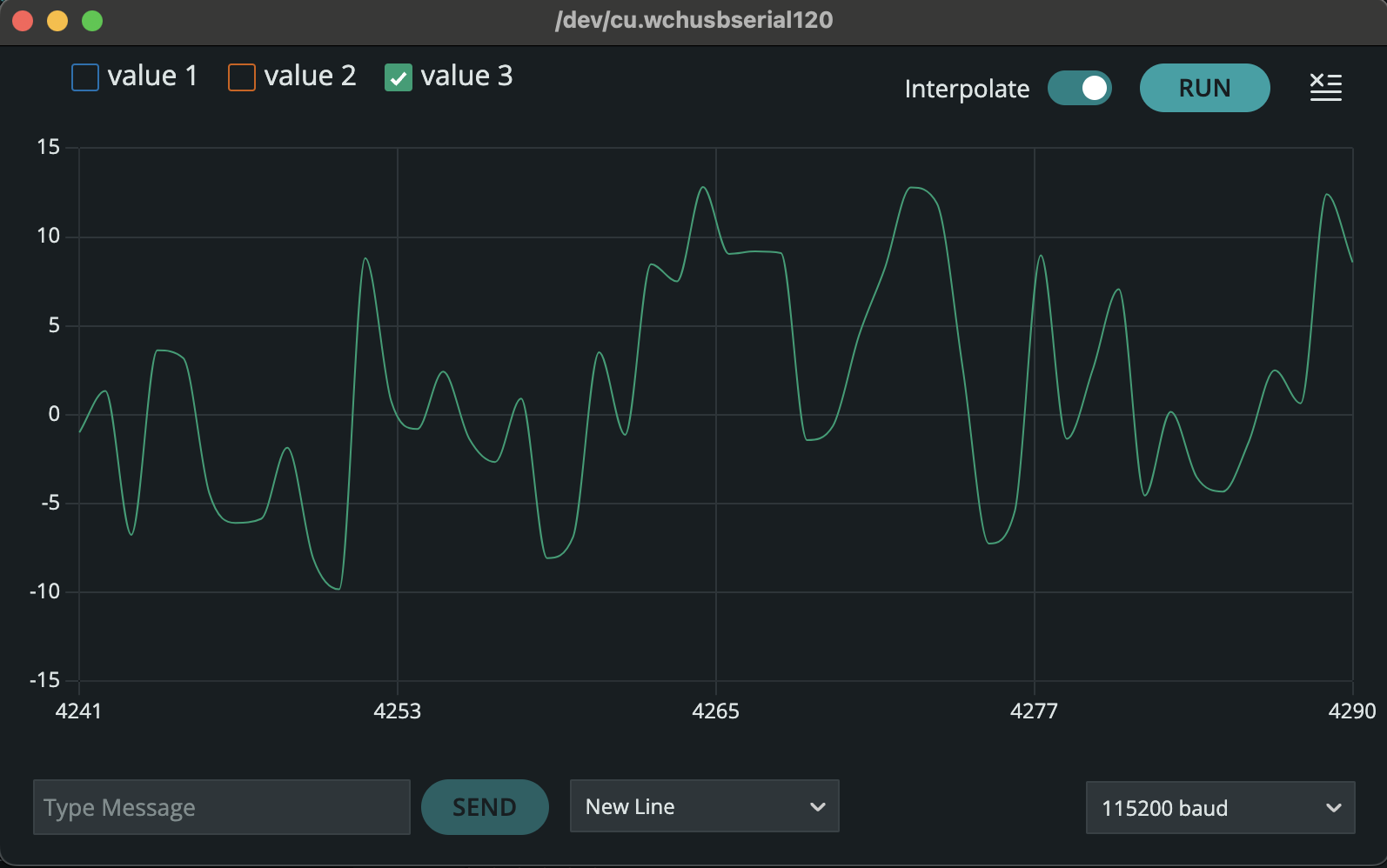
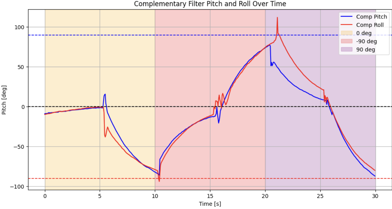
After tuning, I found that an alpha value of \( \alpha = 0.60 \) produced the most stable results. The filter performed reliably within the \(-90^\circ\) to \(90^\circ\) range, but beyond this, the accelerometer's behavior became less predictable. Yaw was left unfiltered since the accelerometer cannot measure it—an interesting limitation given that yaw will be the most relevant parameter in future applications.
Below are the results of my complementary filter, with pitch and roll shown.
To maximize the speed of data collection, I optimized my code by removing unnecessary delays, debug print statements, and redundant operations.
This included eliminating Serial.println() calls between key steps in data collection and Bluetooth transmission that were initially used for debugging.
Additionally, I stored all IMU data in pre-allocated arrays to minimize memory fragmentation and ensure efficient access.
The complete implementation can be seen below.
I adjusted the main loop to collect IMU data only when it was available and when the global IMU_DATA_READY flag was active.
    while (central()) {
        // Store IMU data ready only when available and recording is enabled
        if (IMU_DATA_READY && myICM.dataReady()) {
            compute_complementary_filter();
        }
    }
The compute_complementary_filter() function processes raw IMU data, applying a complementary filter to refine pitch and roll calculations.
The IMU_DATA_READY flag is managed through BLE commands, eliminating the need for manual data collection.
    // Inside handle_command():
    case START_IMU_DATA:
        Serial.println("Starting IMU recording...");
        digitalWrite(LED_BUILTIN, HIGH);
        IMU_DATA_READY = true;
        break;

    case STOP_IMU_DATA:
        Serial.println("IMU recording stopped.");
        digitalWrite(LED_BUILTIN, LOW);
        IMU_DATA_READY = false;
        break;
I then integrated BLE commands into a Python script to initiate and terminate data collection remotely using START_IMU_DATA and STOP_IMU_DATA,
allowing for real-time data logging without modifying the Arduino code manually.
# Start BLE notifications
ble.start_notify(ble.uuid['RX_STRING'], imu_notification_handler)
ble.send_command(CMD.START_IMU_DATA, "")
time.sleep(5)
ble.send_command(CMD.STOP_IMU_DATA, "")The last task was to record a stunt video playing around with the RC car. Overall, I felt it was a really fast car in need of additional tuning. Pretty excited to work on this robot car.
This lab provided hands-on experience with a real-world sensor and the challenges that come with it. I'm looking forward to testing my IMU recording system on the RC car once we integrate the Artemis module.